Mazda 6 Service Manual: Dsc hu/cm inspection
1. Remove the battery and battery bracket.
2. Disconnect the DSC HU/CM connector.
3. Connect the SST
(49 G066 004) to the DSC HU/CM connector and harness side connector.
4. Inspect voltage referring the table below.
Terminal Voltage Table (reference value)
(Ignition switch is at ON, and connector is connected unless indicated otherwise.)


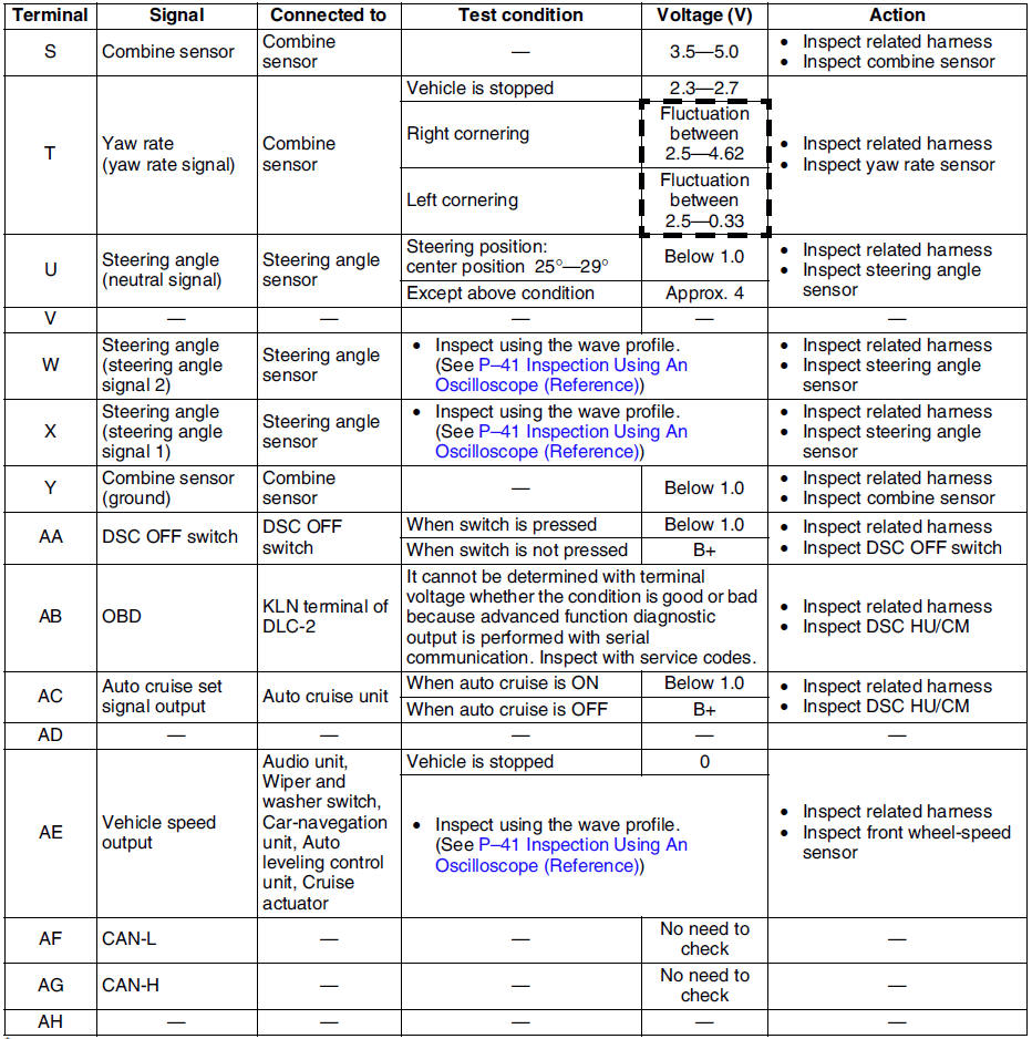
* : Used for vehicle manufacturing, not used for DSC.
Inspection Using An Oscilloscope (Reference)
Steering angle (steering angle signal 1 and 2)
- DSC HU/CM terminal:
Steering angle signal 2 : W ( + ) - R ( - )
Steering angle signal 1 : X ( + ) - R ( - )

- Oscilloscope setting:
1 V/DIV (Y), 25 ms/DIV (X), DC range
- Vehicle condition: Rotating steering wheel at one revolution per second
Note
- As steering wheel rotation speed increases, period of wave shortens.
- As for shape of steering angle signals 1 and 2, the phase is different.
Wheel speed
- DSC HU/CM terminal:
RF : M ( + ) - I ( - )
RR : K ( + ) - H ( - )
LF : F ( + ) - J ( - )
LR : Q ( + ) - N ( - )

- Oscilloscope setting:
1 V/DIV (Y), 2 ms/DIV (X), AC range
- Vehicle condition: Driving 30 km/h (18.6 mph)
Note
- As vehicle speed increases, period of wave shortens.
- If there is malfunctioning in the sensor rotor, wave profile warps.
Vehicle speed output
- DSC HU/CM terminal: AE ( + ) - A( - )

- Oscilloscope setting:
1 V/DIV (Y), 5 ms/DIV (X), DC range
- Vehicle condition: Driving 30 km/h (18.6 mph)
Note
- As vehicle speed increases, period of wave shortens.
 Dsc hu/cm removal/installation
Caution
When replacing the DSC HU/CM, configuration procedure must be done
before removing the DSC HU/CM. If configuration is not completed before
removing the DSC HU/CM, DTC B2477 will be d ...
 Combine sensor removal/installation
Caution
Be careful and do not allow the combine sensor to fall. If by
chance it is subjected to strong impact, replace it.
1. Remove the center console.
2. Remove in the order indicated in ...
Other materials:
Mazda 6 Service Manual: Rear View Monitor
The rear view monitor provides visual images of the rear of the vehicle when
reversing.
WARNING
Always drive carefully confirming the safety of the rear and the surrounding
conditions by looking directly with your eyes: Reversing the vehicle by only
looking at the screen is dangerous as it m ...
Mazda 6 Service Manual: Shift Gear (Shifting) Speed Limit
For each gear position while in the manual mode, the speed limit is set as follows:
When the selector lever is operated within the range of the speed limit, the gear
is shifted.
Shift up
The gear does not shift up while the vehicle speed is lower than the speed limit.
Shift down
The gear d ...