Mazda 6 Service Manual: Refrigerant system service procedures
GAS CHARGING SET INSTALLATION
1. Fully close the valves of the SST
(49 C061 001).
2. Connect the SSTs
(49 C061 002, 49 C061 003) to the high- and low-pressure side joints of the SST
(49 C061 001).
3. Connect the SSTs
(49 C061 006A, 49 C061 007) to the ends of the SSTs
(49 C061 002, 49 C061 003).
4. Connect the SSTs
(49 C061 006A, 49 C061 007) to the charging valves.

RECOVERY
Connect an R-134a recovery/recycling/recharging device to the vehicle and follow the device manufacturer's instructions.
CHARGING
Caution
- Do not exceed the specification when charging the system with refrigerant. Doing so will decrease the efficiency of the air conditioner or damage the refrigeration cycle parts.
Charging Recycled R-134a Refrigerant
Connect an R-134a recovery/recycling/recharging device to the vehicle and follow the device manufacturer's instructions.
Charging Preparation
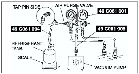
1. Install the SSTs
(gas charging set).
2. Connect the tap pin side of the SST
(49 C061 004) to the air purge valve of the SST
(49C061 001).
3. Connect the SST
(49 C061 005) to the center joint of the SST
(49 C061 001).
4. Connect the SST
(49 C061 005) to the vacuum pump.
5. Connect the SST
(49 C061 004) to the refrigerant tank.
6. Place the refrigerant tank on the scale.
Regular amount of refrigerant (approximate quantity) 470 g {16.6 oz}: L.H.D.
430 g {15.2 oz}: R.H.D.

Evacuation
1. Open all the valves of the SST
(49 C061 001).
Caution
- Close the SST (49 C061 001) valve immediately after stopping the vacuum pump. If the valve is left open, the vacuum pump oil will flow back into the refrigeration cycle and cause a decrease in the efficiency of the air conditioner.
2. Start the vacuum pump and let it operate for 15 minutes.

3. Verify that high- and low-pressure side readings of the SST
(49 C061 001) are at -101 kPa {-760 mmHg, -29.9 inHg}.
Close each valve of the SST
(49 C061 001).

Airtightness Check
1. Stop the vacuum pump and wait for 5 minutes.
2. Check the high- and low-pressure side readings of the SST
(49 C061 001).
- If the reading has changed, inspect for leakage and go to Evacuation. (See Evacuation.)
- If the reading has not changed, go to Charging New R-134a Refrigerant. (See Charging New R-134a Refrigerant.)
Charging New R-134a Refrigerant
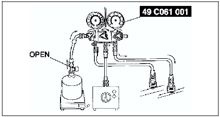
1. Open the valve of the refrigerant tank.
2. Weigh the refrigerant tank to charge the suitable amount of refrigerant.
Warning
- If the refrigerant system is charged with a large amount of refrigerant when inspecting for gas bleakage, and if any leakage should occur, the refrigerant will be released into the atmosphere. In order to prevent the accidental release of refrigerant which can destroy the ozone layer in the stratosphere, follow the proper procedures and charge with only a small amount of refrigerant when inspecting for gas leakage.
- If charging the system with refrigerant using service cans, running the engine with the high-pressure side valve open is dangerous. Pressure within the service cans will increase and the cans could explode, scattering metal fragments and liquid refrigerant that can seriously injure you. Therefore, do not open the high-pressure side valve while the engine is running.
Caution
- Always being charging of refrigerant from the high-pressure side. If changing is begun from the low-pressure side, the vanes of the A/C compressor will not be released and abnormal noise may result.
3. Open the high-pressure side valve of the SST
(49 C061 001).

4. When the low-pressure side reading increases to 0.098 MPa {1.0 kgf/cm2, 14 psi},
close the high-pressure side valve of the SST
(49 C061 001).

5. Inspect for leakage from the cooler pipe/hose connections using the SST (gas leak tester).
- If there is no leakage, go to Step 7.
- If leakage is found at a loose joint, tighten the joint, then go to next step.
6. Inspect for leakage again.
- If there is no leakage after tightening the joint, go to next step.
- If there is still a leakage at the same joint, discharge the refrigerant and then repair the joint. Repeat the charging procedure from evacuation.
Warning
- If charging the system with refrigerant using service cans, running the engine with the high-pressure side valve open is dangerous. Pressure within the service cans will increase and the cans could explode, scattering metal fragments and liquid refrigerant that can seriously injure you. Therefore, do not open the high-pressure side valve while the engine is running.
7. Open the high-pressure side valve of the SST
(49 C061 001) and charge with refrigerant until the weight of refrigerant tank has decreased 250 g {8.83 oz}
from the amount in Step 2.

8. Close the high-pressure side valve of the SST
(49 C061 001).

Warning
- If charging the system with refrigerant using service cans, running the engine with the high-pressure side valve open is dangerous. Pressure within the service cans will increase and the cans could explode, scattering metal fragments and liquid refrigerant that can seriously injure you. Therefore, do not open the high-pressure side valve while the engine is running.
9. Start the engine and actuate the A/C compressor.
10. Open the low-pressure side valve of the SST
(49 C061 001) and charge with refrigerant until the weight of the refrigerant tank has decreased regular amount from the amount in Step 2.

11. Close the low-pressure side valve of the SST
(49 C061 001) and the valve of the refrigerant tank.
12. Stop the engine and A/C compressor.
Leak Test
1. Inspect for leakage using the SST
(gas leak tester).
- If there is no leakage, go to Step 3.
- If leakage is found at a loose joint, tighten the joint, then go to next step.
2. Inspect for leakage again.
- If there is no leakage after tightening the joint, go to next step.
- If there is still leakage at the same joint, discharge the refrigerant and then repair the joint. Repeat the charging procedure from evacuation.
3. Disconnect the SSTs
(49 C061 006A, 49 C061 007) from the charging valves.
4. Install the caps to the charging valves.

REFRIGERANT PRESSURE CHECK
1. Install the SSTs
(gas charging set).
2. Warm up the engine and run it at a constant 1,500 rpm.
3. Set the fan speed to MAX HI.
4. Turn the A/C switch on.
5. Set the RECIRCULATE mode.
6. Set the temperature control to MAX COLD.
7. Set the VENT mode.
8. Close all the doors and all the windows.
9. Measure the ambient temperature and the high- and low-pressure side reading of the SST
(49 C061 001).
10. Verify that the intersection of the pressure reading of the SST
(49 C061 001) and ambient temperature is in the shaded zone.

If not as specified, troubleshoot the refrigerant system. (See TROUBLESHOOTING INDEX.)
REFRIGERANT SYSTEM PERFORMANCE TEST
1. Perform refrigerant pressure check. (See REFRIGERANT PRESSURE CHECK.)
- If they are correct, go to next step.
- If not as specified, troubleshoot the refrigerant system. (See TROUBLESHOOTING INDEX.)
2. Place a dry-bulb thermometer in the driver-side center ventilator outlet.
3. Warm up the engine and run it at a constant 1,500 rpm.
4. Set the fan speed to MAX HI.
5. Turn the A/C switch on.
6. Set the RECIRCULATE mode.
7. Set the temperature control to MAX COLD.
8. Set the VENT mode.
9. Close all the doors and all the windows.
10. Wait until the air conditioner output temperature stabilizes.
Stabilized condition
- The A/C compressor is repeatedly turned on and off based on the A/C compressor control of center panel (manual air conditioner) or climate control unit (full-auto air condtioner).
11. Record driver-side center ventilator outlet temperature.
12. Determine and record ambient temperature.
13. Verify that the temperature reading is in the shaded zone.

- If the performance is not within the shaded zone, troubleshoot the refrigerant system. (See TROUBLESHOOTING INDEX.)
 Service cautions
HANDLING INSUFFICIENT REFRIGERANT LEVEL
If an insufficient refrigerant level is detected at troubleshooting,
do not charge (add) the refrigerant. Because an accurate amount of
refrigerant ca ...
 Basic system
...
Other materials:
Mazda 6 Service Manual: Fuel Requirements
Vehicles with catalytic converters or oxygen sensors must use ONLY UNLEADED FUEL,
which will reduce exhaust emissions and keep spark plug fouling to a minimum.
This vehicle will perform best with fuel listed in the table.
* U.S. federal law requires that octane ratings be posted on gasoline st ...
Mazda 6 Service Manual: Glossary of Terms
Tire Placard:
A label indicating the OE tire sizes, recommended inflation pressure, and the maximum weight the vehicle can carry.
Tire Identification Number (TIN):
A number on the sidewall of each tire providing information about the tire brand and manufacturing plant, tire size, and date of m ...
