Mazda 6 Service Manual: Dsc hu/cm inspection
1. Remove the battery and battery bracket.
2. Disconnect the DSC HU/CM connector.
3. Connect the SST
(49 G066 004) to the DSC HU/CM connector and harness side connector.
4. Inspect voltage referring the table below.
Terminal Voltage Table (reference value)
(Ignition switch is at ON, and connector is connected unless indicated otherwise.)


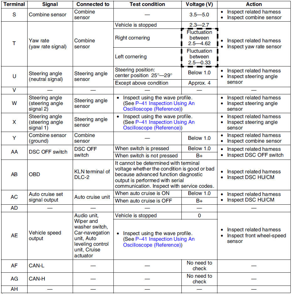
* : Used for vehicle manufacturing, not used for DSC.
Inspection Using An Oscilloscope (Reference)
Steering angle (steering angle signal 1 and 2)
- DSC HU/CM terminal:
Steering angle signal 2 : W ( + ) - R ( - )
Steering angle signal 1 : X ( + ) - R ( - )

- Oscilloscope setting:
1 V/DIV (Y), 25 ms/DIV (X), DC range
- Vehicle condition: Rotating steering wheel at one revolution per second
Note
- As steering wheel rotation speed increases, period of wave shortens.
- As for shape of steering angle signals 1 and 2, the phase is different.
Wheel speed
- DSC HU/CM terminal:
RF : M ( + ) - I ( - )
RR : K ( + ) - H ( - )
LF : F ( + ) - J ( - )
LR : Q ( + ) - N ( - )

- Oscilloscope setting:
1 V/DIV (Y), 2 ms/DIV (X), AC range
- Vehicle condition: Driving 30 km/h (18.6 mph)
Note
- As vehicle speed increases, period of wave shortens.
- If there is malfunctioning in the sensor rotor, wave profile warps.
Vehicle speed output
- DSC HU/CM terminal: AE ( + ) - A( - )

- Oscilloscope setting:
1 V/DIV (Y), 5 ms/DIV (X), DC range
- Vehicle condition: Driving 30 km/h (18.6 mph)
Note
- As vehicle speed increases, period of wave shortens.
 Dsc hu/cm removal/installation
Caution
When replacing the DSC HU/CM, configuration procedure must be done
before removing the DSC HU/CM. If configuration is not completed before
removing the DSC HU/CM, DTC B2477 will be d ...
 Combine sensor removal/installation
Caution
Be careful and do not allow the combine sensor to fall. If by
chance it is subjected to strong impact, replace it.
1. Remove the center console.
2. Remove in the order indicated in ...
Other materials:
Mazda 6 Service Manual: Indicators
Manual shift mode indication
In manual shift mode, the “M” of the shift position indication in the instrument
panel illuminates.
Gear position indication
The numeral for the selected gear illuminates.
NOTE
If the gears cannot be shifted down when driving at higher speeds, the
gear ...
Mazda 6 Service Manual: Front fog light aiming
1. Adjust the tire air pressure to the specification.
2. Position the unloaded vehicle on a flat, level surface.
3. Seat one person in the drivers seat.
4. Position the vehicle 3 m {10 ft} in front of a white screen.
5. While adjusting one fog light, mask the other.
6. Start the engine to cha ...